See the code snippet below, this is just a skeleton of a behavioral code. Don't get afraid with it, it's not that complex. Once I explain it part by part, it will appear very simple and logical. Note that this is only a skeleton part, this will give you an idea how a behavioral code should look like and the keywords used. Please note that all the VHDL keywords are in CAPS. Little modification in this code can provide you skeleton for any other behavioral entity.
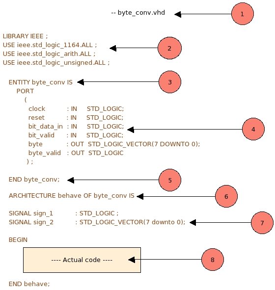
- "byte_conv.vhd" this is just a filename comment. In vhdl, any line can be commented by just putting at least two hyphen "--" at the start of line, this will make whole line commented. These comments are same as in any other language, these will be ignored by compiler and won't affect any functionality or logic. Comments are very important since these helps any one to understand code better, quicker and also makes the codes maintainable.
-
           LIBRARY IEEE ;
           USE ieee.std_logic_1164.ALL ;
           USE ieee.std_logic_arith.ALL ;
	   USE ieee.std_logic_unsigned.ALL ;
The above code of is used to include ieee library packages, hence the very first line mentions library name i.e "LIBRARY IEEE"; below that are the individual packages those are to be included. These packages contain definitions of many basic functions and operators such as AND, XOR, NOT etc. You can create your own packages and use/include them in the similar fashion. Just make sure to compile your packages prior to the entity which is using that package, otherwise the compiler will complain. We will learn about other packages, and creation of our own package in a separate topic. For a time being just understand that these packages are must, and always remember to include them.
-
ENTITY byte_conv isThis line provides entity name information to the compiler. Here "ENTITY" is keyword, "byte_conv" is the entity name or module name, and "IS" again a keyword. It is a good idea to always keep file name same as entity name, this will help you in long run. Note that there is no semicolon at the end of line.
-
    PORT
       (
       clock           : IN     STD_LOGIC;
       reset           : IN     STD_LOGIC;
       bit_data_in     : IN     STD_LOGIC;
       bit_valid       : IN     STD_LOGIC;
       byte            : OUT    STD_LOGIC_VECTOR(7 DOWNTO 0);
       byte_valid      : OUT    STD_LOGIC
       ) ;
Port is the interface through which this entity talks to other entities. Port is a collection of pins, some pins are one bit wide, while other may be multi bit wide or BUS. Through pins declared on these ports, entity gets input, and gives processed data out. For each pin we declare four things.
- Name of the pin
- Direction IN/OUT of the pin, this declares if the pin will be used for input or output. Pins declared as input cannot be used as output, and vice-versa.
- Type of the pin, single pin or bus. Single pin is represented as STD_LOGIC, and buses are represented as STD_LOGIC_VECTOR type.
- Width of pin/pins, in case of single bit wide pin STD_LOGIC declaration is enough. But in case of bus width is indicated by DOWNTO or TO keywords. (7 DOWNTO 0) means total 8 pin bus, MSB bit is 7th and LSB bit is 0th. If TO is used, the declaration will be (0 TO 7) , where bus width is again 8 bits, MSB bit is 7th and LSB is 0th. Always stick to only one type of convention (DOWNTO or TO) in whole design.
-
END byte_conv;
The above line indicates end of interface declaration, where END is keyword and byte_conv is entity name.
-
ARCHITECTURE behave OF byte_conv IS
Jumble up the words to get what it means.. "This is behavioral ARCHITECTURE of byte_conv". This line also means that from here, architecture starts. This architecture will contains two things signal declarations and actual code.
-
SIGNAL sign_1 : STD_LOGIC;
This is the place where we declare signals, now you might be thinking what is this "signal" ? Analogically you can assume that signals are wires. When we rig up circuits on a breadboard we use wires to connect various components. Similarly here also components such as mux, adder, flops which will be in code area needs to be connected. Hence you need wires/signals to connect them. In vhdl this is a place (below ARCHITECTURE declaration and above BEGIN) where we declare all the wires to be used. You can declare as many wires you want, but it is a good practice not to leave unused wires. Once coding of the entity is done, make sure there are no unused wires left. Any signal declaration needs three parameters,
- SIGNAL keyword
- signal's name
- signal's width (bit or bus)
-
      BEGIN

      ---- actual code area

      END behave;
BEGIN is a keywords which indicates that code area begins here, code area is place where we put/code all our digital components such as mux, subtracter, latches, flops etc.., and connect these components using wire/signals declared above. We will understand how to code these components in a separate topic, for time being just understand that this is a code area and all the logic should be put here. The last line "END behave;" is finish line for this behavioral entity.
Thats all with the behavioral coding! In this way we can create a leaf level entity for any block. After coding all the entities in similar way we need to integrate them, integration of these entities are done by instantiating them and connecting them as per our design. For this we use separate type of coding style called structural coding . In our next topic we will cover structural coding .