Since we are already clear with flop flop and adder/subtracter implementation, designing counter is very simple.
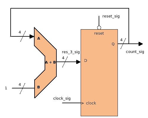
In the above design, flip-flop's output value is given back as adder's one input, and adder's other input is a constant "1".
We know that the flip-flop's output changes only at +ve edge of the clock (for +ve edge flip-flop here). Hence here also, every new value on "res_3_sig" will appear on "count_sig" after next +ve edge. As the flip-flop gets next +ve edge "count_sig" will be updated, and the new value of "res_3_sig" will be computed (incremented by 1). But again, this new value on "res_3_sig" will not be transfer to "count_sig" until next +ve edge arrives. Till next +ve edge output "count_sig" will remain constant.
In this way the output on "count_sig" will keep incrementing on every +ve edge, and after reaching max value the counter will rollover by itself.
The above counter can be coded in vhdl in this way ..
------ Signal Declaration
 SIGNAL res_3_sig : STD_LOGIC_VECTOR (3 DOWNTO 0);
 SIGNAL count_sig : STD_LOGIC_VECTOR (3 DOWNTO 0);

 ------- Coding-------

 res_3_sig <= count_sig + '1';

 flip_flop_process : PROCESS(clock_sig, reset_sig)
 BEGIN
       IF (reset_sig = '0' ) THEN
         count_sig <= "0000";
       ELSIF(clock_sig 'EVENT AND clock_sig = '1') THEN
         count_sig <= res_3_sig;
       END IF;
 END PROCESS;
Here we have implemented an UP counter, similarly a DOWN counter can also be implemented with minor changes in the above design. Just give a try yourself and design a DOWN counter.