-
Integrated Circuit
- IC-1 (555)
- IC-2 (CD4017)
-
Resistors
- R1 (10K)
- VR1 (100K)
-
Capacitor
- C1 (100mfd/ 16V)
-
Diode
- D1-D9 (IN4007)
-
Transistor
- T1 (BC148)
- T2 (BC148)
- T3 (BC148)
-
Miscellaneous
- Three Relays
- Battery (9V DC)
- Neon lamp
- Flexible wires
- Soldering rod etc..
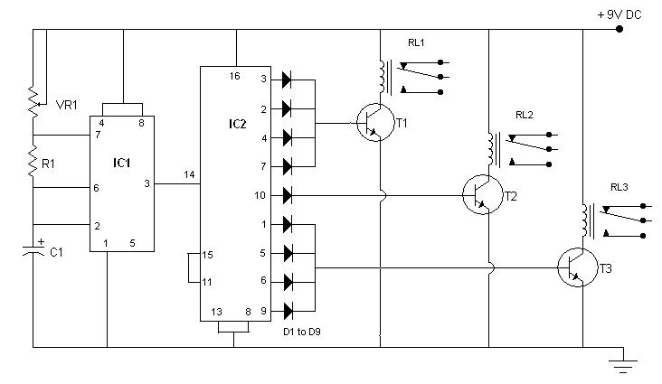
This circuit is self explanatory by its name, and can be used to control traffic in public places, or to demonstrate traffic rules in traffic-parks. IC2, which is heart of the circuit, is a decade counter. In this counter for every pulse fed to pin-14, potential keeps shifting from D1 to D9 in cyclic order. IC1 is used as a pulse generator and generates pulses in regular configurable intervals. These intervals can be changed by varying VR1. The circuit is designed in such a way that out of nine pulses, relay RL1 remains triggered for 4 pulses, relay RL2 for 1 pulse and relay RL3 for remaining 4 pulses. Since D1-D4 provide current to T1, T1 is on whenever there is potential on any diode D1 to D4, which keeps relay RL1 triggered. Similarly other diodes are responsible for RL2 and RL3 triggering. Red, Yellow and Green lamps can be connected to the relays RL1, RL2 and RL3 respectively to complete your mini traffic light controller.