-
Resistors
- R1, R2 (200 Kilo ohms - 1W)
- R3 (100 Kilo ohms - 1/2W)
- R4 (100 Kilo ohms - 1/2W)
-
Transistors
- T1 (BC148B)
- T2 (SL100)
-
Diode
- D1 (IN 4001)
-
Capacitor
- C1 (0.1MF - 50V)
-
Miscellaneous
- Battery, Dry cell -1.5V
- Bulb -3V
- PCB or Breadboard
- Flexible Wire
- Soldering rod etc..
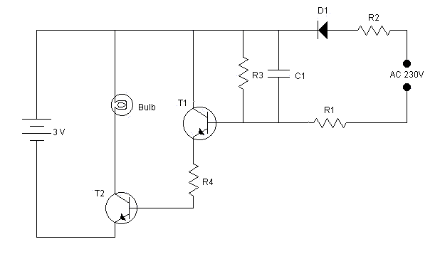
This is a very simple emergency light experiment; advantage of this circuit is that the bulb glows automatically as soon as the AC supply goes off.
If AC supply is present, the alternating voltage is passed through diode D1. D1 behaves as a half wave rectifier and lets only positive voltage to pass on. This positive voltage charges capacitor C1 to a voltage much greater than battery voltage. This condition puts both T1 and T2 in reversed bias, resulting in no current through both the transistor, and keeping the bulb off.
When AC supply goes off, capacitor C1 discharges through R3. Due to this discharging of C1, voltage across C1 decreases gradually. The point when capacitor voltage goes below battery voltage, transistor T1 goes in to forward bias making transistor T2 also in forward bias. Now since both the transistors are in forward bias they provide enough current to flow from bulb, and the bulb glows.
