-
Resistors
- R1 (1kilo ohms, 1/2W)
- R2 ( 18 Kilo ohms, 1/2W)
- R3 (100 ohms, 1/2W)
-
Integrated Circuit
- IC7400
-
Preset
- VR1 (1 kilo ohms)
- VR1 (1 kilo ohms)
-
Capacitor
- C1 (3 mfd , 10V)
- C2 (100 mfd, 10V)
-
LED
- LED1 ( 3V)
- LED2 ( 3V)
-
Miscellaneous
- S1 Push-to-on switch (single pole)
- S2 Toggle switch
- Battery 6V
- PCB or Breadboard
- Flexible Wire
- Soldering rod etc..
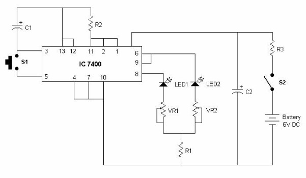
This electronic astrologer answers in either YES or NO. For this reason it is a good idea to put this circuit in a box, and mark one LED as YES, and another as NO. Electronic astrologer can played like this :- You ask such question whose answer can be either YES or NO, e.g Is it going to rain today ?. Now, press and release push-button(S1) to get the answer. After release, the glowing LED is electronic astrologer's answer.
Now lets see how it works! In this circuit IC-7400 is used as multi vibrator. When button S1 is pressed, multi-vibrator starts working, and a low voltage toggles between pin 6 and 8 at very fast rate. As the button is released, low voltage gets latched to any of the pins- 6 or 8. This low voltage provides drain path to the LED connected to it, and that LED glows. This glowing LED becomes astrologer's answer. Note that chanced for each LED to glow is 50%.

