
-
Resistors
- R1 (4.7Kilo ohms, 1/4W)
-
Integrated Circuit
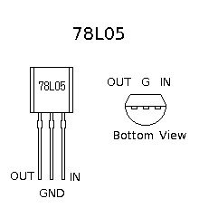
- IC1 (78L05)
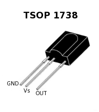
- IC2 (TSOP 1738)
-
Capacitor
- C1 (10uf, 63V, electrolytic)
- C2 (100nf, disc/ceramic capacitor )
-
Miscellaneous
- SUB-D (9 pin) connector
- Infrared Remote (Any TV remote will work)
- Three 1-meter-long wire to connect SUB-D to IR detector Circuit
- PC with Serial/Com Port
- Flexible Wire
- Soldering rod etc..
Imagine you are relaxing and reading your favorite novel while listening to music on your computer, the song just started doesn't suite your mood right now and you want to skip the number. In this situation you have three options, option-1: wake-up the sleeping monitor and change song manually. option-2 : Bare the song, option-3 : Use this small circuit and make your computer obey your wish using any TV remote.
Yes, with this circuit, you can control programs running on your computer by just pressing a button on your remote, like you control your TV.
To control your computer using remote you need two things.
- A Infrared receiver circuit : This detects infrared signals (generated by your remote) and converts them into electrical signals for your computer.
- Infrared Software : This decodes the electrical signals and takes action to controls your program (like mp3 player etc). The action can be any thing like "moving to next song" or "changing volume" etc.
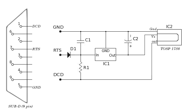
The circuit shown above is a simple Infrared receiver.
Heart of the circuit is TSOP-1738 infrared detector chip. TSOP-1738 detects infrared signals generated by your remote and generates electrical pulses on its out pin. These electrical pulses finally goes into your computer via serial port's DCD pin.
This infrared-circuit gets power from the serial port itself. RST and GND pins provide power to the circuit.
IC1 (78L05) is a 5V voltage regulator, with R1, C1, C2 and D1, IC1 provides clean 5V DC voltage supply to IC2.
DCD, RST and GND of the circuit is connected to respective pins of SUB-D connector using 1m long wire. SUB-D connector should be connected to your computer's Serial/COM port.
Please note that both 78L05 and L7805 are 5V voltage regulator chip but their in/out pin positions are different. Any of the voltage regulator chip can be used provided proper connections are made.
After your Infrared detector circuit is ready you need Infrared software to control your programs. You can download IR POWER infrared software to remote control your programs like mp3 player, media player, power-point presentation etc.