-
Resistors
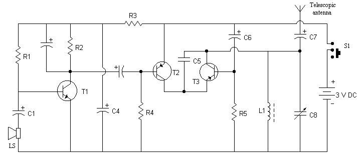
- R1 (220 kilo ohms)
- R2 (4.7 kilo ohms)
- R3 (3.3 kilo ohms)
- R4 (39 kilo ohms)
- R5 (68 kilo ohms)
-
Transistor
- T1 (BC148)
- T2 (2N363)
- T3 (2N481)
-
Capacitor
- C1, C3, C6 (10 mfd, 6V, electrolytic)
- C2 ( 30 mfd, 6V, electrolytic)
- C4, C7 (100 mfd, 6V, electrolytic)
- C5 (120 mfd, 50V, ceramic)
- C8 (4-70 pf, Trimmer)
-
Miscellaneous
- L1 (Oscillator coil of MW radio receiver)
- S1 (Slide switch, single pole)
- LS (Loudspeaker, 8 ohms, 6cm dia)
- Battery (3V or 1.5 x 2 cells)
- PCB or Breadboard
- Flexible Wire
- Soldering rod etc..
This is a very simple circuit, which works on two 1.5V pencil cell. With a telescopic antenna this transmitter can cover 20 to 25 meters.
In this circuit loud-speaker(LS) is used as a microphone to convert sound wave into audio signal. Transistor BC148 works as an audio amplifier, and Transistor 2N481 works as radio frequency oscillator. The transistor 2N363 modulates the audio signal to the carrier radio frequency, produced by the oscillator. The modulated signal is then transmitted to air by telescopic antenna.
This transmission can be listen on any radio receiver by adjusting receiver's frequency. For clear reception, the receiver's and the transmitter's frequency should be same. The transmission frequency of the transmitter can be changed by rotating oscillator coil's core and trimmer's screw.