Now its time to integrate all our behavioral entities in a structural entity. The behavioral and structural code tree depends on the hierarchy. A typical project's behavioral and structural tree hierarchy is shown below
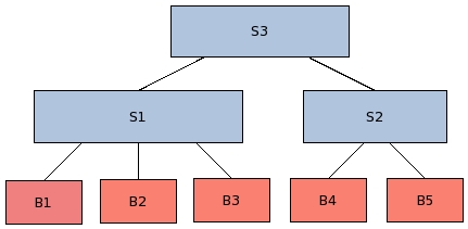
In the above figure you can see that the leaf level entities are behavioral entities and these are instantiated in other structural entity. Structural entity can also be instantiate in other structural entity (as shown above).
For coding any structural entity we do following things..
- Make a structural skeleton
- Declare components
- Instantiate components and connect them, thats all
Lets see the these more closely and develop a structural entity for our case-study project byte converter. Below is the block diagram of case-study project. It looks pretty simple and straight forward since by now you are very much familiar with the architecture.
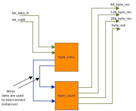
Now lets see its coding, below is code for our structural entity chip.vhd, don't get afraid lets understand it line by line.
 1) LIBRARY IEEE;
 2) USE ieee.std_logic_1164.ALL;
 3) USE ieee.std_logic_arith.ALL;
 4) USE ieee.std_logic_unsigned.ALL;
 5)
 6) ENTITY chip IS
 7)     PORT(
 8)            clock         : IN STD_LOGIC;
 9)            reset         : IN STD_LOGIC;
10)            bit_data_in   : IN STD_LOGIC;
11)            bit_valid     : IN  STD_LOGIC;
12)            64_byte_rec   : OUT STD_LOGIC;
13)            128_byte_rec  : OUT STD_LOGIC;
14)            256_byte_rec  : OUT STD_LOGIC;
15)            byte_out      : OUT STD_LOGIC_VECTOR(7 DOWNTO 0)
16)       );
17)
18) END chip;
19)
20) ARCHITECTURE struct OF chip IS
21)
22)  COMPONENT byte_conv
23)     PORT (
24)          clock       : IN STD_LOGIC;
25)          reset       : IN STD_LOGIC;
26)          bit_data_in : IN STD_LOGIC;
27)          bit_valid   : IN STD_LOGIC;
28)          byte        : OUT STD_LOGIC_VECTOR(7 DOWNTO 0);
29)          byte_valid  : OUT STD_LOGIC
30)         );
31)  END COMPONENT;
32)
33)  COMPONENT byte_count
34)      PORT (
35)           clock         :  IN STD_LOGIC;
36)           reset         :  IN STD_LOGIC;
37)           byte          :  IN STD_LOGIC_VECTOR(7 DOWNTO 0);
38)           byte_valid    :  IN STD_LOGIC;
39)           64_byte_rec   :  OUT STD_LOGIC;
40)           128_byte_rec  :  OUT STD_LOGIC;
41)           256_byte_rec  :  OUT STD_LOGIC;
42)           byte_out      :  OUT STD_LOGIC_VECTOR(7 DOWNTO 0)
43)
44)           );
45)  END COMPONENT;
46)
47)  SIGNAL wire_1 : STD_LOGIC_VECTOR(7 DOWNTO 0);
48)  SIGNAL wire_2 : STD_LOGIC;
49)
50) BEGIN
51)
52)         byte_conv_instance :  byte_conv
53)             PORT MAP (
54)                       clock             => clock,
55)                       reset             => reset,
56)                       bit_data_in       => bit_data_in,
57)                       bit_valid         => bit_valid,
58)                       byte              => wire_1,
59)                       byte_valid        => wire_2
60)                       );
61)
62)         byte_count_instance : byte_count
63)             PORT MAP (
64)                       clock            => clock,
65)                       reset            => reset,
66)                       byte             => wire_1,
67)                       byte_valid       => wire_2,
68)                       64_byte_rec      => 64_byte_rec,
69)                       128_byte_rec     => 128_byte_rec,
70)                       256_byte_rec     => 256_byte_rec,
71)    		          byte_out         => byte_out
72)                       );
73)
74) END struct;
|
- Above is the code of our structural entity called chip, we will keep the file name as chip.vhd. On the left hand side you can see line numbers, these line numbers are not required in code, but I have put them to make reference while explaining.
-
 1) LIBRARY IEEE;
 2) USE ieee.std_logic_1164.ALL;
 3) USE ieee.std_logic_arith.ALL;
 4) USE ieee.std_logic_unsigned.ALL;
These libraries contain basic functions and components required for compilation. For more explanation refer same section in Behavioral Coding
-
6) ENTITY chip ISThis line provides entity name information to the compiler. Here "ENTITY" is keyword, "chip" is the entity name or module name, and "IS" again a keyword. Note that there is no semicolon at the end of line.
-
  6)  ENTITY chip IS
  7)   PORT(
  8)          clock         : IN STD_LOGIC;
  9)          reset         : IN STD_LOGIC;
 10)          bit_data_in   : IN STD_LOGIC;
 11)          bit_valid     : IN  STD_LOGIC;
 12)          64_byte_rec   : OUT STD_LOGIC;
 13)          128_byte_rec  : OUT STD_LOGIC;
 14)          256_byte_rec  : OUT STD_LOGIC;
 15)          byte_out      : OUT STD_LOGIC_VECTOR(7 DOWNTO 0)
 16)       );
Above is a port declaration of entity in terms of pins. For each pin we declare four things.
- Name of the pin.
- Direction IN/OUT of pin, this defines if the pin is input pin or output.
- Type of pin, single pin or bus. Single pin pins are represented as STD_LOGIC, and buses are represented as STD_LOGIC_VECTOR.
- Width of the pins, in case of single bit wide pin STD_LOGIC declaration is enough. But in case of bus, width is indicated by DOWNTO or TO keywords. For example (7 DOWNTO 0) or (0 TO 7). Always stick to one convention (DOWNTO or TO) in whole design.
-
18) END chip;
This line indicate end of interface declaration, where END is keyword and chip is entity name.
-
ARCHITECTURE struct OF entity IS
Jumble up the above words to get its meaning, "This is a structural ARCHITECTURE of entity". This line also means that from here, architecture starts. This structural architecture will contain three things; component's interface , instance of components and connection between instances using wires or signals.
-
 22) COMPONENT byte_conv
 23)     PORT (
 24)          clock       : IN STD_LOGIC;
 25)          reset       : IN  STD_LOGIC;
 26)          bit_data_in : IN STD_LOGIC;
 27)          bit_valid   : IN STD_LOGIC;
 28)          byte        : OUT STD_LOGIC_VECTOR(7 DOWNTO 0);
 29)          byte_valid  : OUT STD_LOGIC
 30)         );
 31) END COMPONENT;
 32)
 33) COMPONENT byte_count
 34)    PORT (
 35)          clock        :  IN STD_LOGIC;
 36)          reset        :  IN STD_LOGIC;
 37)          byte         :  IN STD_LOGIC_VECTOR(7 DOWNTO 0);
 38)          byte_valid   :  IN STD_LOGIC;
 39)          64_byte_rec  :  OUT STD_LOGIC;
 40)          128_byte_rec :  OUT STD_LOGIC;
 41)          256_byte_rec :  OUT STD_LOGIC;
 42)          byte_out     :  OUT STD_LOGIC_VECTOR(7 DOWNTO 0)
 43)
 44)         );
 45) END COMPONENT;
Here is the component declaration of two components, "byte_conv" and "byte_count". In vhdl we need to declare a component before we make instance of that. It is very important to note, that in vhdl any design will be a tree of instances, if you compile a entity but don't make its instance, then it wont be taken in to design. We will use this component declaration and make its instance below.
This is also place where signals should be declared, (below ARCHITECTURE declaration and above BEGIN). -
50) BEGINBEGIN is a keywords which indicates that code area begins here, since we have already declared our both the components above, here in code area we will make instance of those components and connect them, thats all!
-
52) byte_conv_instance : byte_conv
Yes making instance is this simple, just give any instance name "byte_conv_instance" in this case, put colon ":" and then component's name.
-
After making instance, we need to connect this instance's pins. See below how each pin is connected.
 53)       PORT MAP (
 54)                 clock             => clock,
 55)                 reset             => reset,
 56)                 bit_data_in       => bit_data_in,
 57)                 bit_valid         => bit_valid,
 58)                 byte              => wire_1,
 59)                 byte_valid        => wire_2
 60)                 );
Pin connection starts with keyword "PORT MAP", yes! understand it as, how port of this instance is mapped or connected. Note that clock is connected to clock, this means that pin clock of the chip entity will directly get connected to this instance's clock. Similarly "reset" is connected to reset, and other data pins too. Note that pins byte and byte_valid are not connected directly, but are connected through wires (wire_1, wire_2). Since these pins are not coming from top but are connected between the instances.
Always remember that, to connect pins between two instance you always require wires/signals, you can't simply connect them directly. Also remember that the wire's width should also match with the two ends where it is going to be connected, otherwise compiler will flag number of errors. e.g To connect byte from byte_conv to byte_count, we have used wire_1 which is 8 bit wide.
Also note that output of any instance can be directly connected to the top pin, if it is not going to other instance.
-
74) END struct;
The last line "END struct;" is finish line for structural entity.
With this we finished structural coding. By now, we know how to code behavioral and structural entities. Before moving ahead make sure that you are clear up till here. Now in the next topic we will understand how to code internal logic for behavioral entities.. Yes, this is very important topic, and place to show your designer skills. caution: Also remember that this is a place where most of bugs keep hiding :) So all the best..