
CRC Generator
Copyright © Electronic Designworks
Version 1.0
KEY FEATURES
-
Generates Synthesizable VHDL RTL code
-
Parallel CRC computation
-
Configurable data bus width
-
Selectable standard CRC polynomial from preset list
-
Configurable user defined CRC polynomial
-
User programmable Initial value
-
User selectable first bit (MSB/LSB)
-
User selectable clock (Positive/Negative Edge)
-
User selectable reset (Active LOW/HIGH)
OVERVIEW
Data corruption is the major problem associated with data transmission. Whenever data is transmitted over medium (optics/cable/wireless) there is a finite probability that the data might get corrupted. Hence it is very important that receiver should be able to check if the data received is corrupted and take required measures (e.g. receiver may request transmitter to resend the data).

To deal with this problem checksum method is used. Transmitter computes checksum(CRC) over the data and sends it along as shown in Fig-1. At the receiver end, receiver freshly recomputes the checksum (CRC) over received data and compares it with the received checksum(CRC). If both the checksum(CRC) matches, the received data can be assumed error free. Electronic Designworks provides CRC generator IP which can be used at transmitter for CRC checksum generation, and at the receiver end for CRC verification. The generated CRC module is Synthesizable VHDL RTL hence may be used easily in any FPGA or ASIC application.
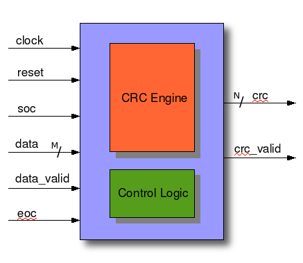
PIN INTERFACE
|
SL No |
Pin Name |
Direction |
Width (bits) |
Description |
|
1 |
clock |
IN |
1 |
clock to crc engine |
|
2 |
reset |
IN |
1 |
reset to crc engine |
|
3 |
soc |
IN |
1 |
start of crc. One clock pulse along with the first data to initialize the initial values. data_valid must be asserted with this indication. |
|
4 |
data |
IN |
M |
data on which the crc has to be computed. This data is validated with data_valid. Those data for which data_valid ='1' will only be taken-in for crc computation, data for which data_valid = '0' will be ignored. *M bits, user configurable while code generation |
|
5 |
data_valid |
IN |
1 |
data_valid pin validates input data, only data for which data_valid pin = '1' will be taken-in to the crc engine. Data for which data_valid = '0' will be ignored. |
|
6 |
eoc |
IN |
1 |
end of crc indication. One clock pulse, along with the last data. Indication of last data to the crc engine. data_valid must be asserted with this indication |
|
7 |
crc |
OUT |
N |
Computed crc will be available on these pins. CRC is valid only when crc_valid = '1'. *N bits, user configurable while code generation |
|
8 |
crc_valid |
OUT |
1 |
When crc_valid = '1' indicates that the crc computation is done and crc checksum is available on crc pins. When crc_valid = '0', crc pins may contain intermediate crc value which may not be used. |
TIMING DIAGRAM
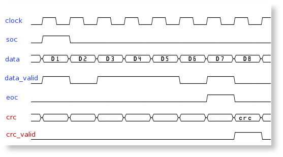
Timing diagram
-
Positive edge clock is assumed
-
soc (start of crc) signal is one clock pulse
-
data_valid is asserted with soc
-
eoc (end of crc) signal is one clock pulse
-
data_valid is asserted with eoc
-
data_valid is asserted only for D1, D3, D4, D5 and D7, hence crc checksum will be computed only on these data. Other data D2 and D6 will be ignored.
-
on the next clock after eoc, crc checksum is ready which is indicated by crc_valid signal.
HOW TO USE CRC GENERATOR
Following user options are provided in CRC generator
Clock selection

User can select clock option, Positive-edge selection will generate the "CRC engine" which works on positive edge and negative edge selection generates "CRC engine" which works on negative edge.
Reset Selection

When Active-Low is selected, "CRC engine" will be under reset when reset pin is equal to '0'. When selected Active-High, "CRC engine" will be under reset when reset pin is equal to '1'.
First Serial

This selection provides option to specify which bit to consider as first bit in data. If MSB is selected, crc will be computed from MSB to LSB. If LSB is selected, crc will be computed from LSB to MSB.
Data Bus Width

User can specify input data bus width, data-bus-width is in terms of bits.
Polynomial
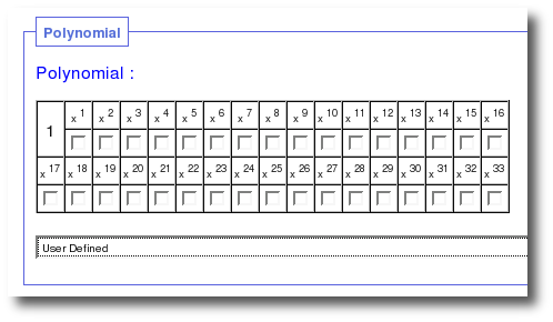
User is free to specify his/her own polynomial by selecting appropriate polynomial coefficients through check-box.
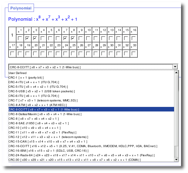
User can also select standard polynomial from the drop-down list.
Initial Value
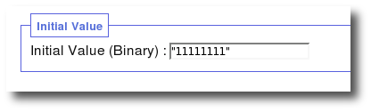
CRC engine gets initialized with this initial value. The Initial-value is specified in binary. Size of the initial-value field (number of bits) gets automatically computed from the polynomial used, but user free to change the value. e.g user is free to change initial value from all ones “11111111” to all zeros “00000000” as per the requirement. It is suggested that to keep the size (number-of-bits) same since it gets derived from the polynomial specified.
NOTE : CRC Generator uses Javascript to calculate "Initial Value" width (number of bits). When Javascript is disabled, It is user's responsibility to specify correct width of "Initial value" for error free code generation!