-
Resistors
- R1 (1K, 1/4W)
- R2 (100K, 1/4W)
- R3 (68K, 1/4W)
- R4 (68K, 1/4W)
- R5 (2.2K, 1/4W)
-
Capacitor
- C1 (2.2uF)
- C2 (1uF)
- C3 (2.2uF)
-
Transistor
- T1 (SL100)
-
Diodes
- D1 to D8 (1N4148)
- D9 (1N4001)
-
Integrated Circuit
- IC1 (CD4017)
- IC2 (CD4071)
- IC3 (CD4081)
- IC4 (CD4069)
-
Miscellaneous
- S1 to S10, push buttons
- Relay 12V, 200 ohms
- Battery 12V
- PCB or Breadboard
- Flexible Wire
- Soldering rod etc..
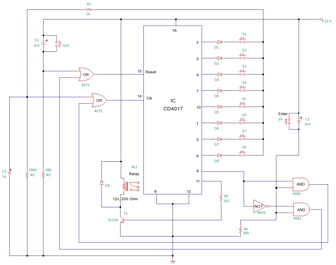
This is a simple but efficient Electronic lock. This lock can be used to protect any electronic systems from unauthorized usage. To get access the uses needs to know 8 digit pass-code or password. When the user enters correct 8 digit password followed by "Enter" button, it activates the relay allowing access to the system controlled by relay. If the 8 digit pass-code is incorrect, after pressing "Enter" button, the circuits reset's itself without turning the relay on.
Heart of the circuit is IC1 (4017) decade counter. At power up, the counter will be at zero count and only pin-3 of IC1 will be high. If switch S1 is pressed momentarily it will provide a clock pulse for the counter which will increment the count and move high value from one pin to another (counting pulses) < /br> For example after power-on, only pressing S1 will switch high value from pin-3 to pin-2. After that only pressing S2 will move high value from pin-2 to pin4. Hence by pressing S1 to S8 sequentially, the high level on the pins shifts from pin-3 to 2 -> 4 -> 7 -> 10 -> 1 -> 5 -> 6-> and finally to pin-9. Only and only when ping 9 is high, pressing the "Enter" button will activate the relay and the clock will get opened. Any wrong-entry will reset the sequence. This circuit can be intentionally reseted by pressing the "Reset" button (S10). Switches S1 to S8 can be given random display numbers, and their random placement will make it difficult to guess the pass-code ( may be placing them as 3x3 switch matrix). One or more parallel connection switches of S10 can be placed in between S1 to S8 to increase the complexity of the code, so that any random pressing will repeatedly keep reseting the circuit and not allowing any access.
IC2 (CD4071), IC3 (CD4081) and IC4 (CD4069) are used to provide logic so that the circuit gets reset if incorrect pass-code is entered. This circuit can be simplified by reducing this specific logic, which also means compromising the strength of the lock. * NOTE : To alter the pass-code of this combination lock, you simply re-wire the switches.