| Positive-edge Flip-Flop |
|---|
|
 VHDL CODE
1) flop_process : PROCESS(clk_sig, reset_sig) 2) BEGIN 3) If(reset_sig = '0') THEN 4) ff_out_q_sig <= '0'; 5) ELSIF(clk_sig 'event AND clk_sig = '1') THEN 6) ff_out_q_sig <= data_bit_sig; 7) END If; 8) END PROCESS; |
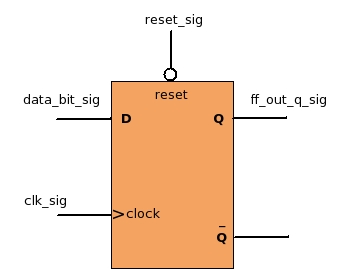
- Flip-Flops are coded as a process. At Line 1 you can see "flop_process" this is process name, user can give any name. After keyword "PROCESS" you can see two signals reset_sig and clk_sig these are sensitivity list signals.
-
This process gets executed, when any signal's value present in the sensitivity list changes. The sensitivity list may contains many signals separated with coma ', if any signal's value changes, the process will get executed once.
Since we want the code to behave as a positive edge flip flop, where the output changes either on the positive edge of the clock, or when the reset = '0'. Hence we have kept clock and reset in the sensitivity list. Now when ever clock or reset signal changes, this process will get executed and new value of ff_q_out_sig will be computed.
If you understood the sensitivity concept, its great. If not, you need not worry. For now just understand that for any clocked (flip flop) process, reset and clock should in the sensitivity list. -
In flip-flops "reset" should have highest priority (higher then clock). If the reset is active, flip flop should be under reset state, giving out '0' at the output.
Hence to model this behavior we have kept if reset condition first. Where we are checking if the reset is equal to '0' (since our flip-flop has a active low reset as shown in diagram) then the output will be zero ignoring input and clock (line no 3,4). - Since clock is present in the sensitivity list, this process will get executed on every +ve and -ve clock edges. But we wanted to code +ve edge flip-flop where the output changes only on the +ve edge. For this, care has been taken in the code. If you carefully observe the condition at line 5 (clk_sig 'event AND clk_sig = '1') . The condition says when the clock clk_sig ticks, and when clk_sig = 1. Both the conditions are true only when clk_sig changes from 0->1 i.g positive edge. Hence even though the process gets executed on both the edges, the output changes only on +ve edge.
- When flip flop is not under reset then on every +ve edge of clock, the output "ff_out_q_sig" should take the current value of input "data_bit_sig" (line no 6), which is what a +ve edge flip flop does.
-
If you want to tie "ff_out_q_sig" to "Q BAR" then simply change code at line 6 to
ff_out_q_sig <= NOT data_bit_sig;