Now, suppose you thought a great circuit to solve some practical problem. You know how the circuit should behave for each and every input. But the problem is, you don't know how to combine these logic gates to get that solution. Since the same design can be implemented with N number of ways, each consuming different number of gates, how to make sure that the circuit is using least number of gates ? Depending on the complexity of circuit, it may not possible for you to try out all the combination to hit the most efficient one.
To solve all the above issue there is a method called Karnaugh map. Lets see, how to use karnaugh map ? and what other information is required to use karnaugh map effectively.
- The essential requirement is that, you should know output of your circuit for each and every input. e.g Suppose your circuit takes 3 inputs, then you should know the circuit's output for each and every eight input combinations.
- It is better if you list down the required output for every input in a separate sheet of paper.
- There may be some input combinations, which your design doesn't bother, or there may be some combination which you know will never occur. e.g Suppose you circuit takes 4 bit counter value at the input, but the counter rolls only from 0 to 9 and then goes back to 0. In such scenario your circuit doesn't bother about input value 10 to 15. Such values are called DON'T CARE CONDITIONS.
- One should aware of these DON'T CARE CONDITIONS in a design. These helps karnaugh map to reduce the gate usage to the optimum.
- The number of output bits you need in you design, will decide the number of karnaugh maps required.
Now, lets see how to use it. It is very simple..
- Fill up the karnaugh map table with the output requirement i.e 0, 1 or X (Don't care).
- Apply karnaugh map rules.
- A karnaugh map provides a logic solution in terms of boolean expression.
- Since, for each output bit a separate karnaugh map used, the number of boolean expression will be equal to the number of output bits in design.
- Finally, replace your gates as per the expressions, and your design is ready.
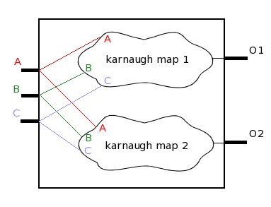
The figure above shows a design example. The design takes 3 inputs, and generates 2 outputs. From the figure it is clear that 2 karnaugh maps will be required, since 2 outputs are present. Each karnaugh map will take all 3 inputs to generate its output. Each karnaugh map will provide a boolean expression which will satisfy its input and output requirement. Both the boolean expression will finally provide logic circuit required for the design.

Lets take another example and try to implement it through karnaugh map. Suppose we need to design a circuit which takes 2 inputs and generates 1 output. The design should give out '1', when inputs are "00" or "11". And should generate '0' for other input combination. First list down this requirement...
                             A   B  |  out
                           --------------
                             0   0  |   1
	                     0   1  |   0
                             1   0  |   0
                             1   1  |   1
With karnaugh map the design will look some thing like shown below...
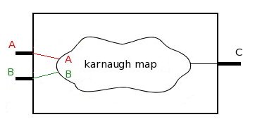
Lets see in details how a karnaugh map can be implemented.

Above is shown a karnaugh map table for two input circuit. The two input pins A and B are marked at the top. In the image below horizontal red section shows possibilities on input pin A, and vertical red section showing possibilities on input pin B.
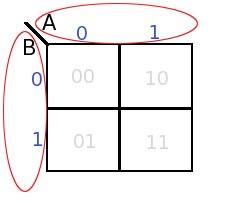
The two inputs can have 4 input combinations, each of these combinations are show with grey values in each box.
Remember we have already listed the requirement, now we will fill the karnaugh map with our requirement. The grey marking will help you to place the requirement in appropriate box.
After the map is filled, it will look like this....
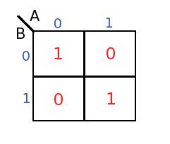
Observe the above map carefully, the first 1 is required when both the input are "00". which means if we NOT the inputs and AND them, it should generate first 1. So the boolean expression for first 1 will be..
 - -
 A.B
Similarly, the second 1 should be generated when both the inputs are 1 i.e "11". which means if we just AND the inputs then it should generate second 1. The expression for the second 1 is
A.B
At this point let me introduce one rule, the rule says...
"all the individual ones in the circuit should be OR-ed to get final boolean expression"
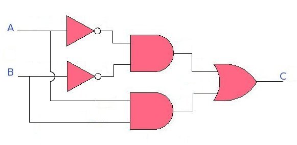
Now as per the rule we should OR all the ones to get the final expression, hence the final expression will be
- -
A.B + A.B
Now lets replace the expression with gates to get the final Circuit (shown below)...
We will see other examples of karnaugh map in next part.
