We have seen various properties of opamp. Now we will put opamp in various scenarios and will try to analyze its output behavior. Here i would like to introduce on more term "stability", a circuit is stable if every part says it is ok!, below we will also try to guess various output voltages (opamp's) to see if the circuit is stable.
Note that for all the example below, the power supply pins +Vcc and -Vcc are not show, but you can assume that these pins are connected to +12V and -12V DC supply. Also assume that gain of opamp used in the circuit is 1000000.

1) Below is shown a circuit where +2V is applied to inverting input, and +5V is applied to non-inverting input. Now what should be the output ?
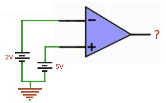
From our study of opamp, we know that if voltage at +ve pin is greater than -ve pin, the opamp swings toward +ve voltage. And the voltage value is calculated by equation..
output_voltage = [voltage_at_non_inv_input - voltage_at_inv_input] * gain
applying this formula we get,
output_voltage = [5-2] * 1000000
                    = 3000000 V
But practically our opamp won't be able to go upto 3000000 Volts because +Vcc itself is 12V. Hence at output opamp will give +12V.
Answer : 12V DC
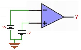
2) Now in the next circuit +5v is applied to inverting input, and +2V is applied to non inverting input. Here what should be the output ?
We will again use the equation..
output_voltage = [voltage_at_non_inv_input - voltage_at_inv_input] * gain
Applying this formula we get...
output_voltage = [2-5] * 1000000
                    = -3000000 V
Here also, opamp won't reach till -3000000V because it will be again limited by -Vcc. Hence the output will be -12V.
Answer : -12V DC
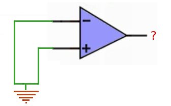
3) In this circuit both inverting and non-inverting inputs are grounded or 0V is applied to both the inputs. In this case what should be the output ?
We will use the equation again..
output_voltage = [voltage_at_non_inv_input - voltage_at_inv_input] * gain
output_voltage = [0-0] * 1000000
                    = 0 V
Hence, Ideally the output should be 0V.
Answer : 0V DC
4) Here comes the good one, output is connected to the inverting input, and +12V is applied at non-inverting input. Here what should be the output ?
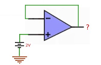
For this circuit lets guess some outputs and see if the circuit is stable..
Say 0V should be at output..
Now output is 0V, then inverting input should also be 0V, now the equation says...
output_voltage = [2-0] * 1000000
		    = 2000000 V
                    = 12V (max Vcc)
But this is not true, since at first place we have assumed that output is 0V. This means that with 0V, circuit is not stable.
It seems we have found the problem, because of the large gain and feedback connection, the guessed values are not making circuit happy (stable).
Now we should think some value, so that the difference between input is very small, and when this difference is multiplied by gain, the output should be very close to guessed value, making opamp stable.
Say 1.999998 is at output...
output_voltage = [2-1.999998] * 1000000
		    = 2 V
                    = 2V
1.999998 seems to be a good value, because 1.999998 brings the equation very close to 2V (guessed) and the opamp will be stable here.
This is the beauty of feedback, opamp is not saturated (+VCC or -VCC) and also found a stable voltage by itself (2V).
Answer : 2V DC
5) Lets analyze the circuit below, don't rush, take your time to analyze behavior of this circuit.
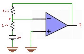
From last circuit we have observed that opamp circuit (with feedback) is stable when voltages on both the inputs are almost same. In this case non-inverting input is grounded, and inverting input is getting feedback from output through resistors. Now if this circuit to be stable voltage at inverting input should be same as voltage at non-inverting input i.g 0V. This means that voltage at point P shown should be 0V.
Lets simplify the circuit as shown below..
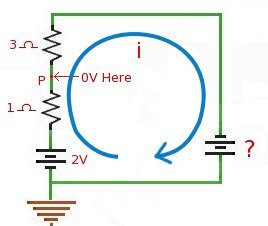
We know that at point P voltage should be 0V. Value of current i flowing through circuit can be calculated from the section between P and ground.
i = V/R
= 2/1
= 2A
This 2A current should also flow through 3 Ohms resistor and the unknown voltage should provide this current. Lets calculate this unknown voltage...
V = I x R
= 2 x 3
= 6V
And for the direction of current shown, this voltage should be -ve, hence -6V should appear at opamp's output.
Answer : -6V
6) Now to the same circuit described above, in put is fed with varying signal, say 1V peak to peak sine wave, then what should be the output ?
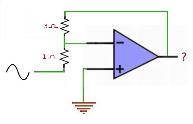
To this circuit we already calculated that for 2V input output is -6V. Similarly if you recalculate for 1V input you will get output as -3V. Hence this circuit behaves as an amplifier with gain -3. Gain for same circuit with different values of resistor can be calculated as..
gain = - Rf/Rin (where Rf is feedback and Rin is input resistor)
= - 3/1
= -3
And Voutput = - (Rf x Vin) / Rin
Hence for a sine input of 1v peak to peaks this circuit will output inverted sine wave of 3 volts peak to peak.
Answer : 3V peak to peak inverted sine wave
7) In the circuit below every thing is same, except the resistor values are changed. This type of circuit you will generally find in books, but it is not so understandable for new reader. Here what should be the output ?
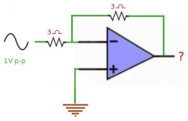
We know (from previous circuit) that this is an inverting amplifier, where the gain is calculated by -Rf/Rin.
Voutput = - (Rf x Vin) / Rin
Voutput = - 1 x Vin
Hence output will be inverted sine wave with -V peak to peak.
Answer : 1V peak to peak inverted sine wave